Karaoke Machine
A microphone and speakers with inputs for music!
This project focused on designing and building a functional karaoke system to provide hands-on experience in electronic system design. The objective was to create a system with two audio input channels, a microphone and an auxiliary input capable of delivering clear, noise-free sound through speakers. The design incorporated essential features such as volume control, microphone gain adjustment, and input protection while adhering to specific performance criteria and constraints. This project emphasized practical skills in circuit design, prototyping, and system integration.


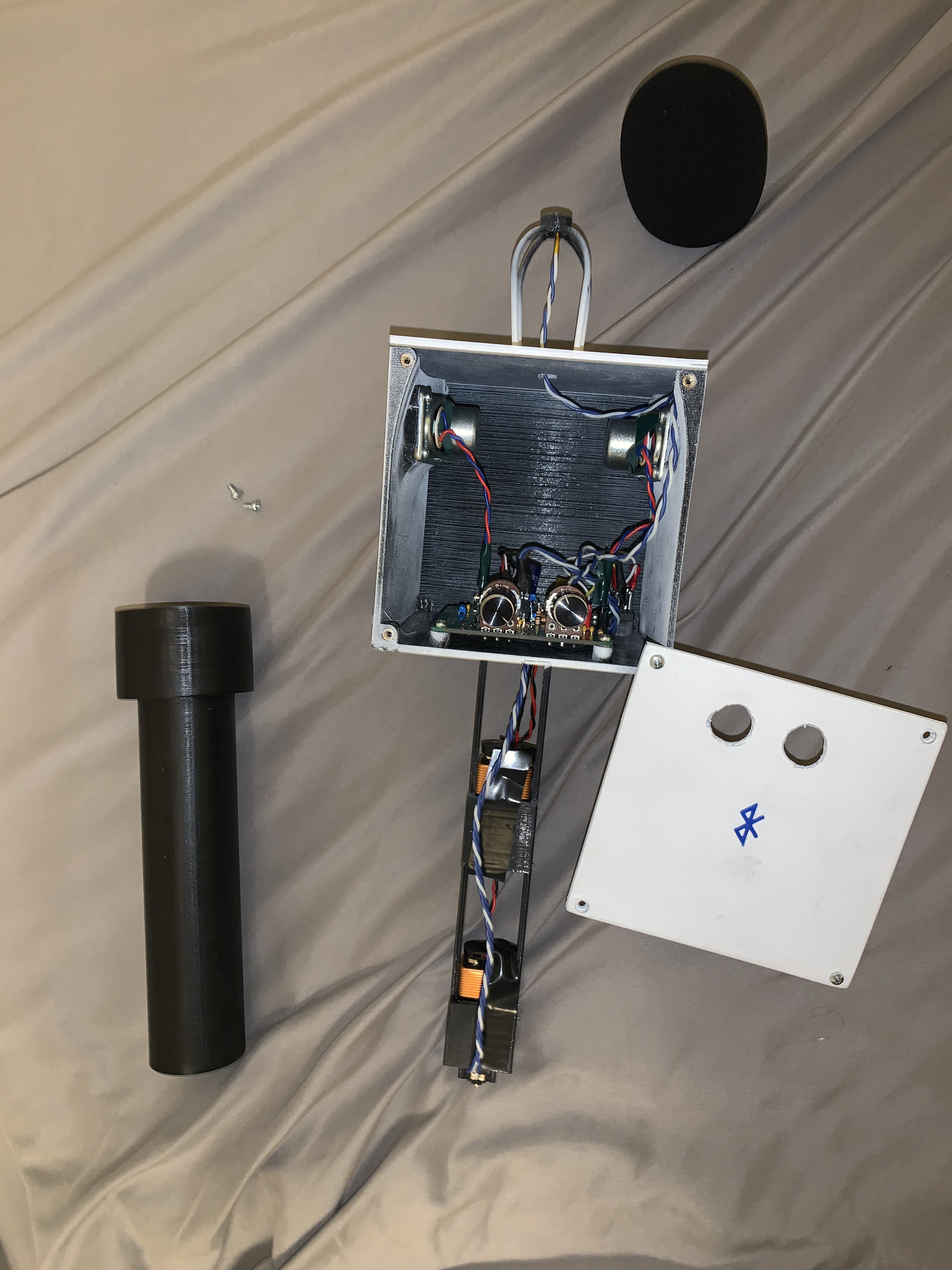
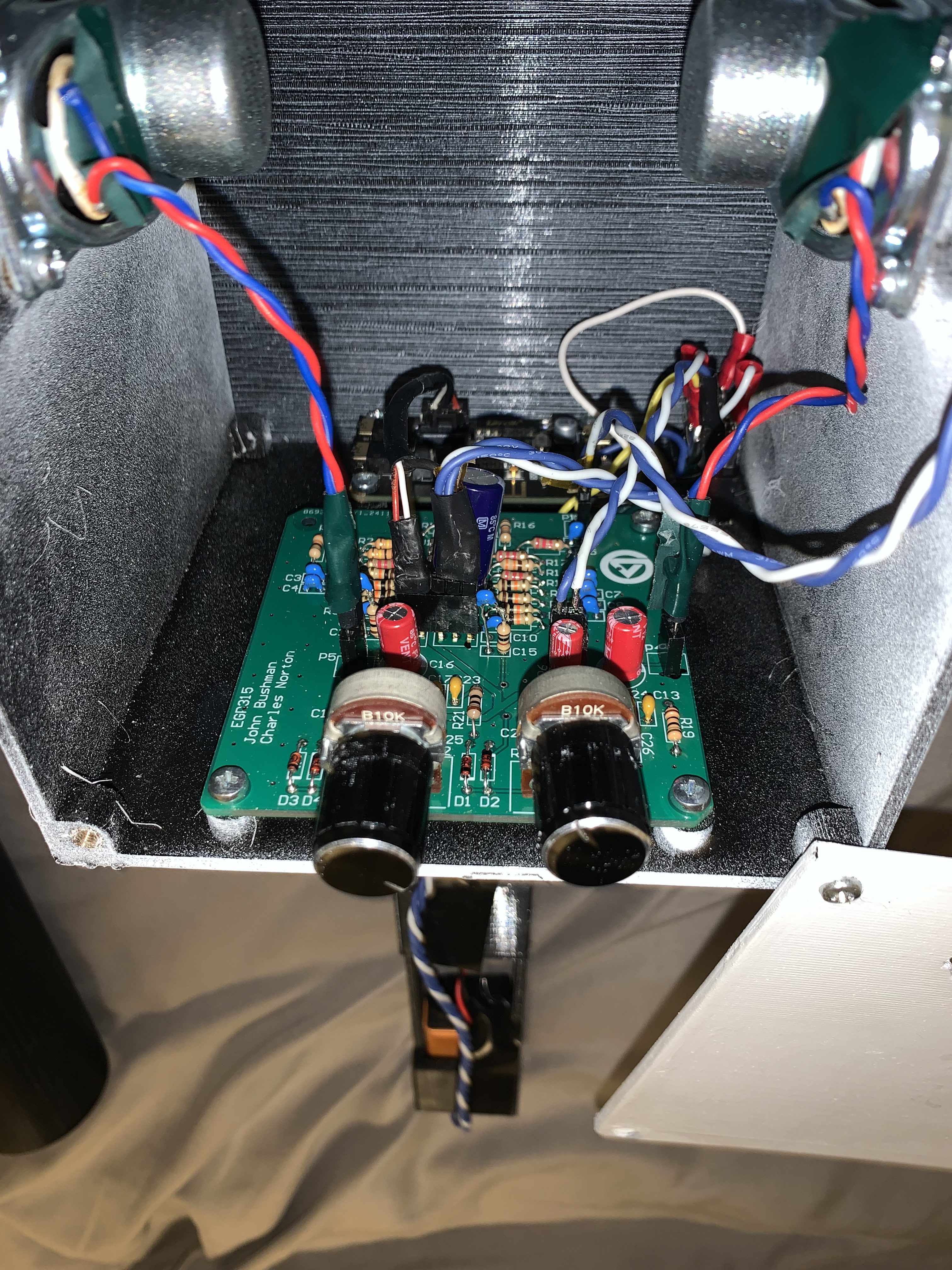
Project Requirements
This project focused on the development of a dual-input audio system designed to accommodate both a dedicated microphone circuit, incorporating a microphone and preamplifier, and an auxiliary (Aux) input for integration with external stereo audio sources such as smartphones, laptops, or portable music players. A fundamental objective was to achieve clear and low-noise mixing and conditioning of the incoming audio signals before their amplification and output to two 8 Ω speakers, each requiring a minimum power delivery of 1 W. User interaction was facilitated through dedicated controls for master volume and microphone gain adjustment.
Beyond the core requirements, several potential enhancements were explored to expand the system’s functionality. These included the independent routing of the left and right channels from the Aux input to their respective speakers, the addition of Bluetooth connectivity as an input.
It’s important to note that the project was supplied with a single set of primary components. Also, the printed circuit board (PCB) design required thorough validation prior to manufacturing, which was estimated to have a turnaround time of up to two weeks. Ultimately, the success of this project was to be evaluated based on the fulfillment of the defined functional requirements, the quality of the circuit design, and the effectiveness of team collaboration, as assessed through peer feedback.
System Design and Implementation
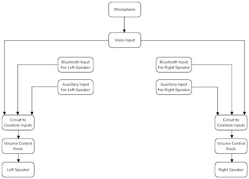
The system had two summing circuits combining the left and right audio from the auxiliary and bluetooth inputs. The output to the summing amplifiers then goes to a potentiometer for volume control, before going to an audio amplifier and the speaker.
Audio/Power Amplifier Subcircuit
To satisfy the requirement of stereo sound the two identical and independent audio amplifier circuits were created.
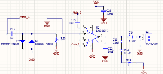

The audio Amplification circuit starts with the signal passing through a DC-blocking capacitor. The next part of the amplification circuit was a voltage limiting circuit which limited the input voltage to 1.1V. The signal then passes through a 10 kΩ potentiometer. Finally, the signal is amplified using an LM386 audio amplifier IC which was set up for a gain of 20 V/V. To achieve a gain of 20V/V, capacitors 19, 20, 21, and 22 were depopulated. The signal then passed through a 470 $\mu$F capacitor before reaching the speaker.
Summing Amplifier Subcircuit
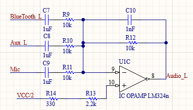
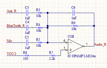
The right and left audio summing circuits both take inputs from the bluetooth module, the microphone circuit, and the auxiliary port. Each signal passes through a DC-blocking capacitor before entering the summing circuit. The summing circuit has a gain of 1V/V and a DC bias of VCC/2 or 4.5V. Resistors 13 and 14 for the Left circuit and 7 and 8 for the right circuit were placed at the non-inverting input to limit bias current corruption.
Microphone Subcircuit
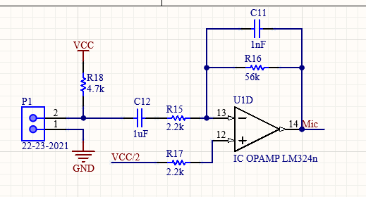
The microphone subcircuit amplifies the output of the microphone by a gain of 25.45 V/V, the output of the microphone is connected to P1. The circuit has a DC bias of VCC/2 or 4.5V. Resistor 17 was used to limit the effects of bias current. Capacitor 12 was a DC-blocking capacitor and capacitor 11 was placed as a high-pass filter to reduce high-frequency noise.
Power Supply Subcircuit

The voltage follower circuit is set up with a voltage divider to set the positive terminal to the op-amp to VCC/2 or 4.5V. Capacitors 2 and 27 were set as decoupling capacitors near the source input and input to the op-amp to reduce noise to the circuit.
Testing
Power Requirement
To test the 1 W power requirement of the speaker, the speaker was disconnected and a 0.5 Vp 1 kHz sine wave was applied from a function generator to one of the summing amplifier inputs. The output signal was then recorded using an oscilloscope. Then the voltage gain was calculated and the power of the output signal was determined.
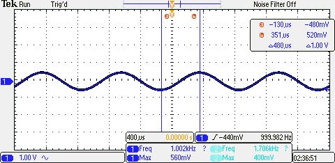
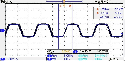
The voltage gain of the circuit was calculated to be 1.76 V/V. With an output load of 10 Ω, the average power of the output signal was calculated to be 38.72 mW, effectively meeting the requirements.
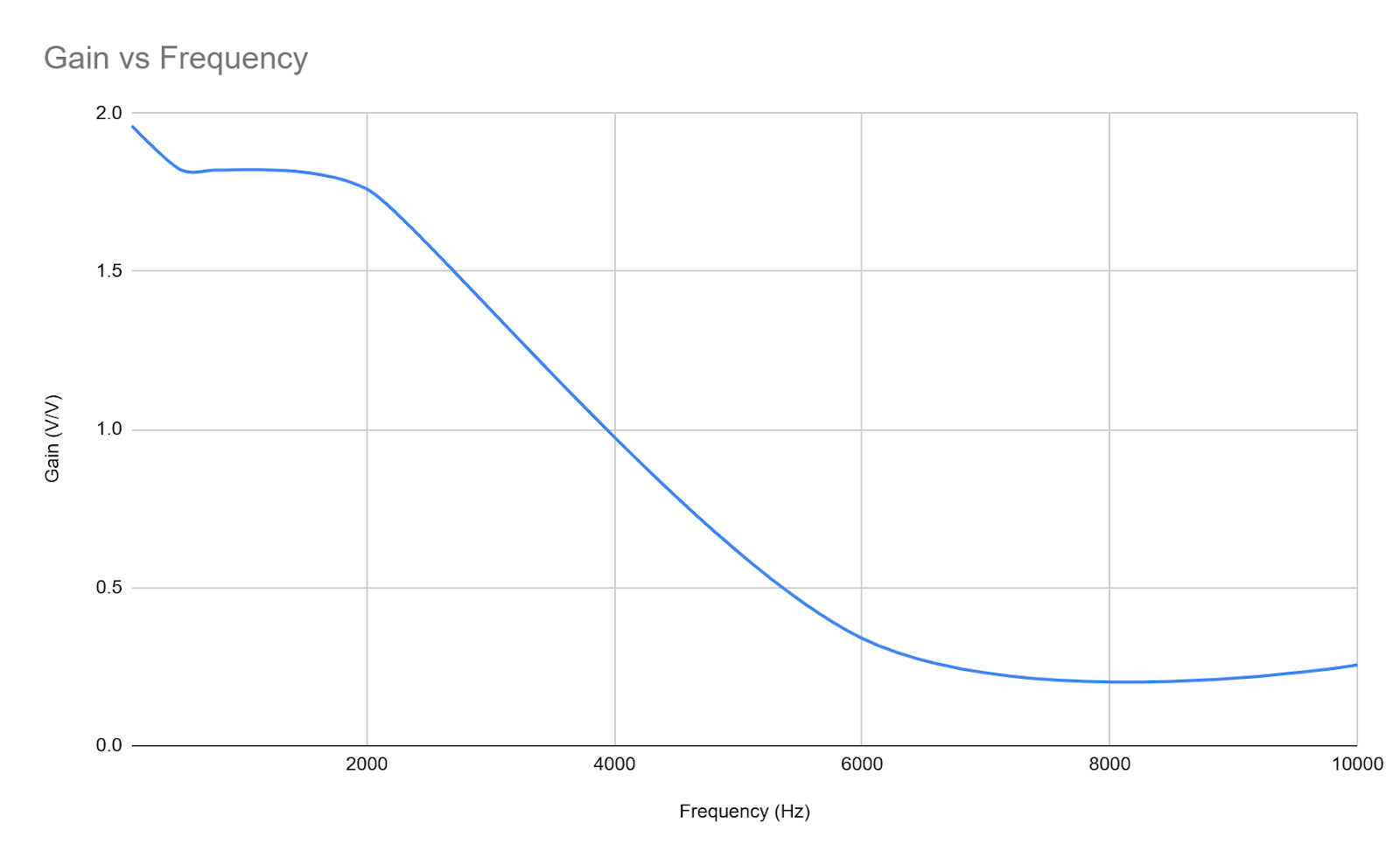
Gain vs Frequency
A Gain vs Frequency plot was created to have a visual of the system’s response.
Remarks
At the end of the karaoke system project, it was determined that the design and implementation successfully met the majority of the functional requirements. The system was designed and built to include two audio input channels: a microphone circuit with an electret microphone and a preamplifier, and an auxiliary input capable of interfacing with devices such as cell phones, laptops, or music players.
The system effectively drove two 8 Ω speakers with less than 1 W of power delivered, as evidenced by the testing results. User controls, including volume control and microphone gain adjustment, were integrated.
The power supply was designed to be versatile, allowing power to be supplied via batteries. The components were securely and attractively housed in a fixture, meeting the fixture and housing requirements.
Testing results confirmed that the system performed as expected. The voltage gain and power output of the audio signals were within the specified parameters, and the system was able to handle various input frequencies and audio sources without distortion.
The design and implementation of the karaoke system were largely successful in achieving the required objectives. The system demonstrated clear, noise-free sound, effective user controls, and robust power supply options.