Line Following Robot
A robot designed to follow a line on the ground
Working with two other teammates, we tackled the challenge of building a robot that could follow a line using an Arduino Uno and a QTR reflective sensor array. The big aim was speed – getting it around a set course as quickly as we could. But, there was this extra bit where it also had to recognize reflective panels that would be randomly placed along the track. Basically, it had to nudge them to know it saw them and then keep going.
I personally had a good time playing a major part in the system for navigating the course and the steering system.
Our team’s effort landed us a first place finish among 15 other teams of students.


Navigation
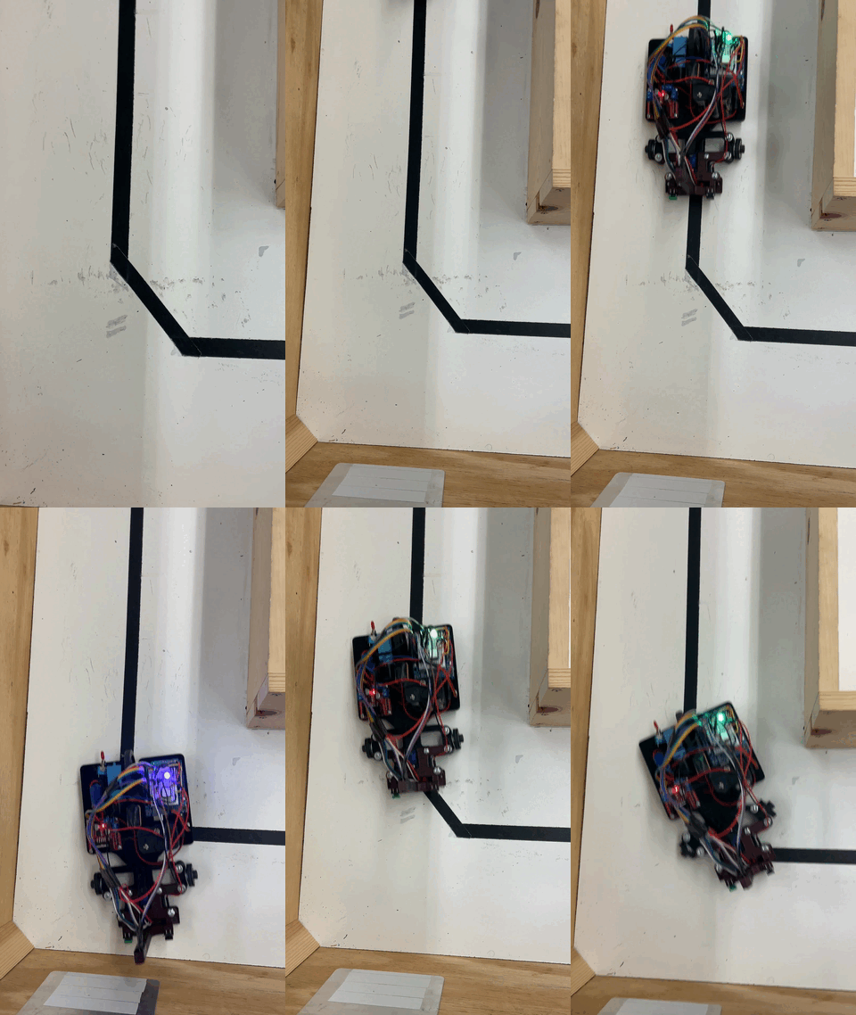
So, how did we actually make the robot follow the line? Well, using a pre-made library, the QTR sensor array gave us a range of values from 0 all the way up to 7000. Think of it like a little eye that tells us where the black line is with respect to the sensor. A reading of 0 meant the line was way over to the right of the sensor, and 7000 meant it was all the way to the left.
My job was to take that raw data and turn it into something the robot could understand for steering. I basically created a simple, linear map.

The sensor reading was the input, and the output was the value that controlled our steering servo. So, if the sensor saw the line way over on the right (close to 0), the mapped value would tell the servo to crank the wheels hard to the right. Conversely, if the line was on the far left(close to 7000), the servo would get the command to turn sharply left.
Two different mapping functions had to be made to effectively navigate the robot. Ideally this would be one mapping function, but this would have been ineffective because the the value that centers the servo didn’t exactly line up with centering our steering.
Looking at the right turn case in the picture above, a line equation can be derived:
\[y=\frac{67}{350}x+750\]Likewise, a line equation can be derived for a case that would require the robot to turn left.
\[y=\frac{78}{350}x+640\]So then, the following piece-wise function can be constructed
\[y=\begin{cases} \frac{67}{350}x+750 & & 0\leq x<3500 \\ \frac{78}{350}x+640 & & 3500\leq x\leq 7000 \end{cases}\]Where $y$ is the value written to the function that controls the servo and $x$ is the value being read from the QTR sensor
This linear mapping also took care of the deviations from the line. If the robot started to drift off, say to the right, the sensor readings would drop towards 0. That mapped value would then continuously tell the servo to steer harder and harder to the right until the line was back under the sensor. It was a constant, real-time correction – the robot was always ‘looking’ at the line and adjusting its course.
Sensing IR Reflectors
Now, once we had the robot navigating the track, we had to tackle the next part of the challenge: making sure it could ‘see’ and acknowledge those reflective panels.
To do this, we rigged up an IR pair. We had an IR emitter constantly sending out IR light. Then, we used an IR receiver to detect that light. This receiver was wired up with a resistor, creating a voltage divider.

Basically, the more IR light the receiver picked up, the higher the voltage it sent back to the Arduino, which we read as an ADC value. So, when the robot got close to a reflective panel, which would bounce that IR light back, the ADC value would jump up. We set a threshold, and when the ADC value crossed that line, we told the robot, ‘Okay, you’ve seen a panel!’ and switched it into a special ‘drive straight’ mode. This worked out great because the reflective panels were always placed in a way that the robot would end up driving straight towards them.
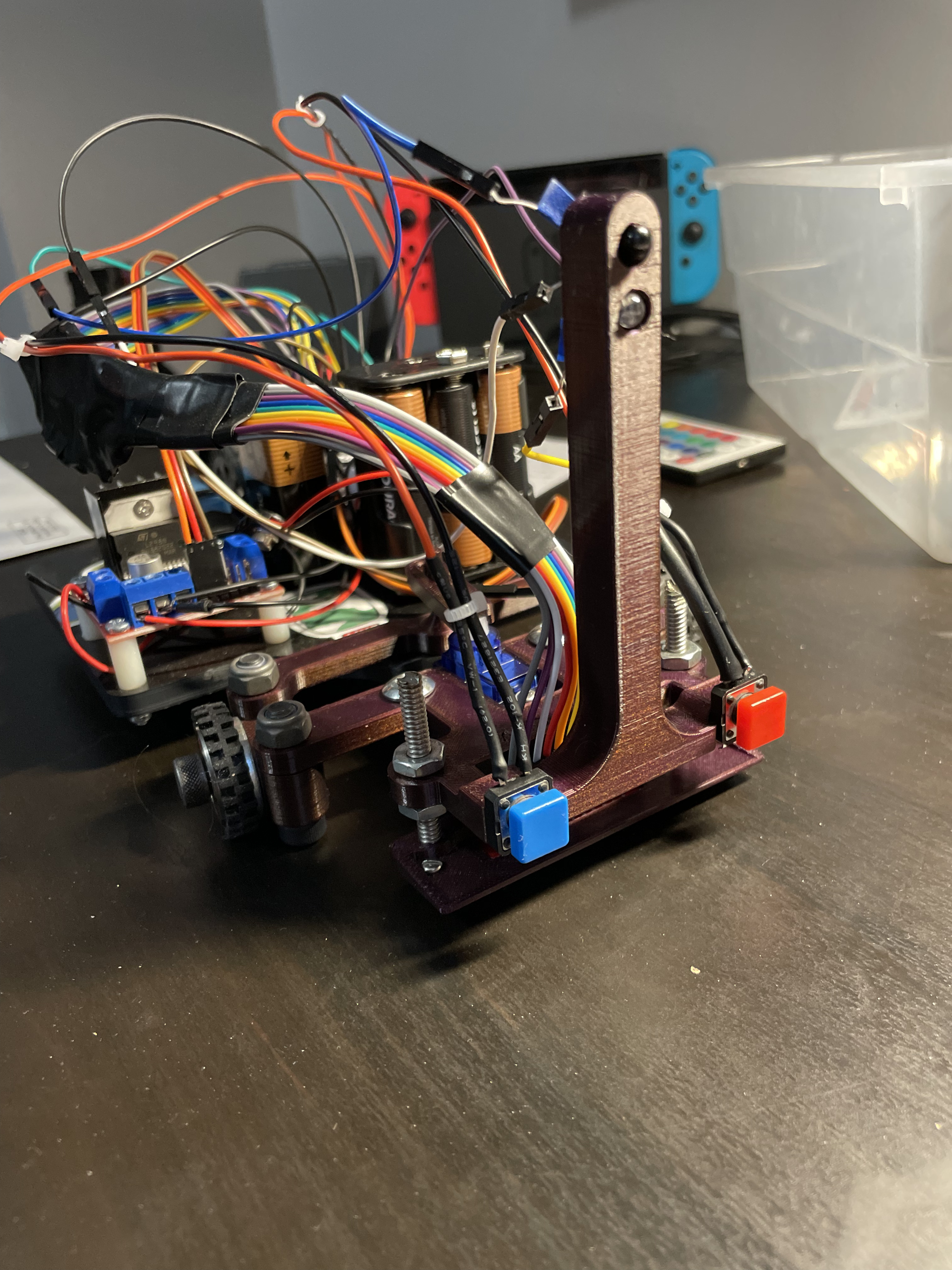
To make sure the robot knew when it had really reached the panel, we added a bumper at the front. When the robot bumped into the wall (or panel), a little momentary switch on the bumper would get triggered. This was like the robot saying, ‘Okay, I’m here!’ and we programmed it to back up a bit before going back to its line-following mission.
State Diagram of the Line Following Robot
